- Table of Contents
- Introduction
- Where to start?
- Super Simple World Generation
- Small Improvements
- The Final Result
Introduction
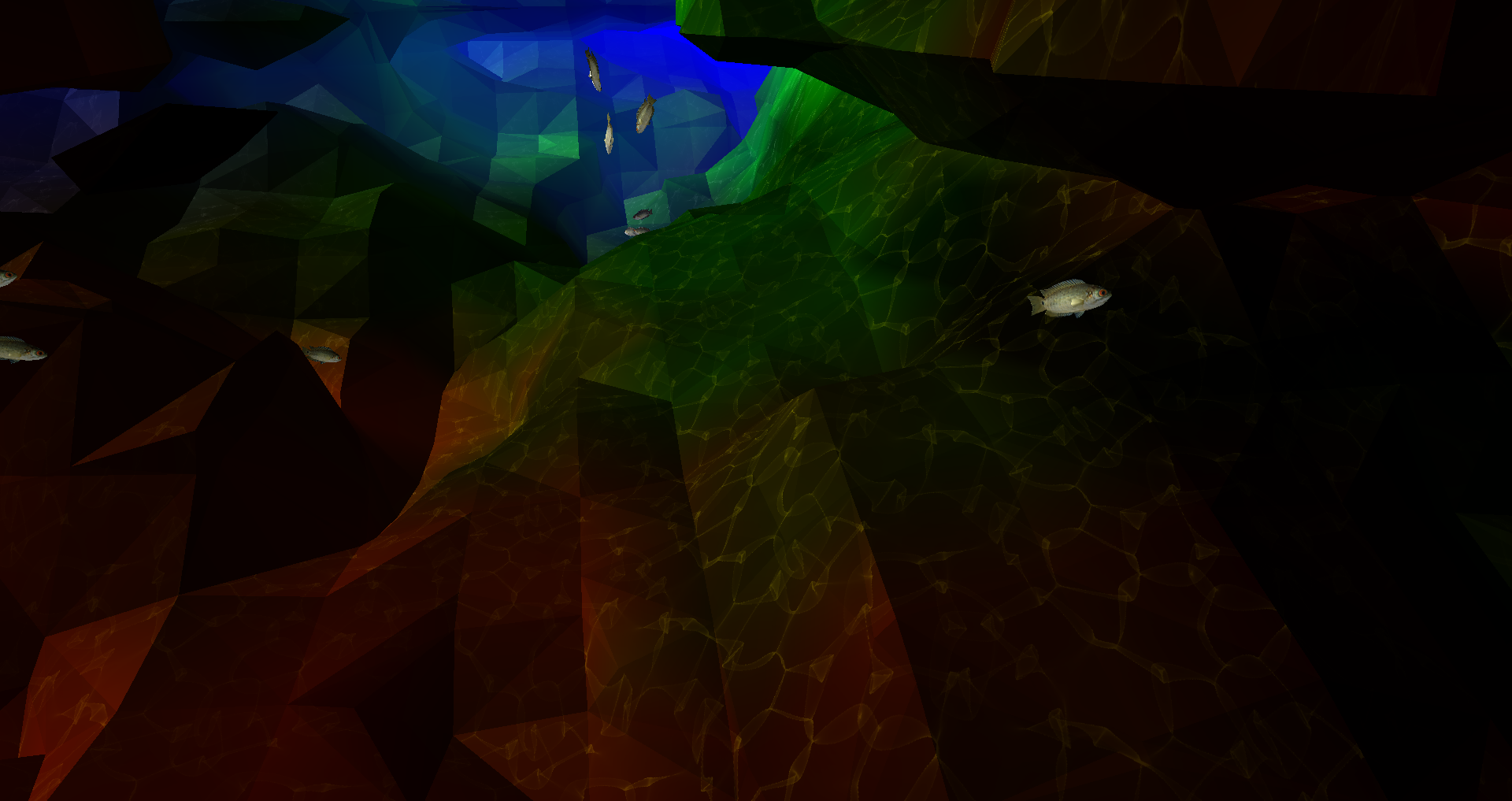
This picture shows the final result of a 2-semester long project to construct an underwater scene in C/OpenGL. It took a lot of work to get to that point as almost everything had to be written from scratch. There are no fancy libraries or game engines, just pure pain. Before I get too far into this, this is not some highly original concept. I was inspired to recreate this scene from the video below. I’ll also be borrowing some ideas to make this all work.
Where to start?
It’s hard to figure out how to get going on a project like this. What should come first, the fish or the terrain? I decided on starting with Boids and pushing the nightmare that is terrain generation onto the backlog.
Boid’s algorithm isn’t really a tough egg to crack. For those that are unfamiliar, it’s just 3 simple rules:
- Separation - Boids want to be close to each other, but not too close, apply a strong repulsive force if boids get too close to one another.
- Alignment - Try to point in the same direction as other boids around you.
- Cohesion - The opposite to separation, move towards the centroid of nearby boids. This causes boids to want to stay together.
Put visually:

See Boids - Background and Update, Craig Reynolds for more details.
That’s really it, for now. We’ll come back to this later.
Super Simple World Generation
Okay, I may have lied; this part was sheer pain. Anyway, let us get into it. Inspired by the video linked above, I wanted to generate a world with the Marching Cubes algorithm - Marching Tetrahedra struck me as a bit intimidating.
What is a marched cube?
The marching cubes algorithm explains how to generate a set of triangles to approximate a scalar vector field. More simply, if you have points in a 3d space, this is how you generate triangles to approximate a ‘surface’ that those points would create. Don’t worry too much if my 2-sentence crash course didn’t do the trick, there’s going to be some helpful graphics below.
Generating World-like Scalar Vector Fields
Marching cubes is not something that will generate a world in isolation. There has to be some sort of input. Marching cubes take in a function and outputs a set of triangles. So what should that function be? Well, the good news is that I don’t have to solve this problem. Smarter people have come along and tackled this a long time ago. Perlin noise is a multidimensional function which when paired with marching cubes produces life-like terrain. Again, we’ll visualize this process below, keep going!
It should be noted that I’ll use Simplex & Perlin Noize interchangeably here. For all intents and purposes, they’re the same thing, Simplex is much faster.
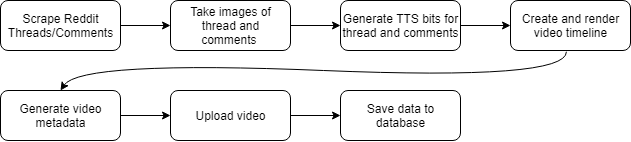
The basic approach
Here’s the 4-step plan to get the world generation working:

In hindsight, it was not that easy.
First Try
The above shows my first crack at my 4-step plan. There are also a few boids in there - because why not. It may be apparent that this is pretty terrible. Firstly, we need some colors. This could be done in so many different ways, the approach I went with is using the noise function to generate a lower frequency function mapped to a color. So when I assign a noise value to a point, I also generate a color value.
Next, the size of the world has to be a lot larger. I had a small world initially because the program was terribly unoptimized. The problem is that I have an awesome GPU capable of handling these complex calculations in parallel but instead chose to do each calculation sequentially on the CPU. For prototyping this was fine, but it was time to get into the nasty stuff.
Shaders
Before, all the work for drawing the world was being done on the CPU. This is only okay for small amounts of work. In my case, I wanted to recreate the entire world every frame so the CPU was not going to cut it. While a CPU has maybe 8 cores, a GPU has many, many, more cores. This means that parallel workloads can be completed much faster. Moving the relevant calculations over to the GPU is not a trivial task.
Firstly, a VBO is assigned. This is a block of memory reserved in the GPU for our calculations. Ideally, we will write to this memory space with our input data, kick off the calculations, and ask for the GPU to write the resultant triangles to the active frame buffer. I could spend a long time explaining my horror stories of this process, but it’s easier to show you instead:
How did I fix it? No idea. But my hard work did pay off. Now the world is a bit larger and it has colors!
Back to Boids
So you may have noticed that the boids disappeared in the last video. They have not been forgotten about. A lot of work is needed to integrate them into the shader hellscape I have just created. Firstly, we need them to spawn around the player. Since the world is infinite, we cannot spawn a set amount of fish and call it a day. To accomplish this, I broke the world up into 9 chunks relative to the player. When a chunk is too far, it gets deleted. When a new one is created, it’s populated with a bunch of new boids.
Terrain Collision
When the boids move throughout the world, they better not phase through anything. If this were Unity, we’d throw on a box collider and call it a day. OpenGL gives you nothing of that sort. So collision detection and avoidance will have to be written entirely from scratch.
Firstly, if we’re a boid, how do we know if we’re about to hit something? If you said anything to do with sight, you’re completely wrong. As written, this program does not store the state of the world. It’s regenerated every frame inside the GPU. The game itself does not know about the definition of the world.
Instead, we have to perform a voxel-raycast outwards from the perspective of the boid, generate the world geometry from the voxel raycast, and perform ray-triangle intersections with the generated geometry and the boid’s velocity vector.
Voxel Raycasting
For those unfamiliar, a raycast is the process of shooting a ray and performing operations at different points along that ray. For this, I used A Fast Voxel Traversal Algorithm for Ray Tracing.
This is a quick visualization I made of a blue ray intersecting 4 red voxels (interactive):
Ray-triangle Intersection
So, we have the cells we need to test. Next, the cells are passed in as points to the world generation algorithm to create the world’s triangle geometry. Once we have the triangles, the ray has to be tested to see if it hits any of the triangles. If it does hit, we have to steer the boid away.
The ray-triangle intersection is a relatively easy problem to understand and solve if you do not want to go crazy on the optimization. When you throw away the need for performance, it’s just 3 steps:
- Calculate the intersection between the ray and plane formed by the face of the triangle.
-
Calculate the cross-products of the sides of the triangle to the point
What do we mean by this? Let us start with this diagram:
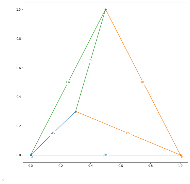
Now make your right hand into this:
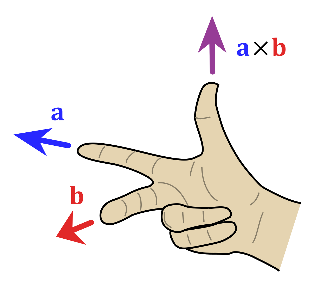
If AB is a and AS is b, then your thumb points out of the triangle, the same direction as the triangle’s normal vector. But now imagine that the point AS is below the triangle. If you do the same thing you have to flip your hand around (no > 180 degrees allowed). That means that your thumb would oppose the normal vector.
- If all resultant vectors are pointing in the same direction as the normal vector, the ray intersects the triangle.
The code is unbelievably simple:
# A,B,C are triangle points
# S is the ray origin
# D is the ray direction
def intersects(A, B, C, S, D, color='red'):
    # N = The normal vector of the triangle
    N = cross(A - B, B - C)
    N /= norm(N)
    # Force the normal to oppose the ray
    if (dot(N, D) > 0): N = -N

    # t defines the length of ray needed to intersect the plane
    t = dot(N, A - S) / dot(N, D)

    # dot(N, D) could be zero, member to do a <=zero check
    # dot(N, D) == 0 means that the ray and plane are parallel
    if (abs(dot(N, D)) > 0.001 and t > 0):
        PlanePoint = S + D * t

        PN = [
            cross(B - A, PlanePoint - A),
            cross(C - B, PlanePoint - B),
            cross(A - C, PlanePoint - C)
        ]

        PN = [pn / norm(pn) for pn in PN]

        intersect = all([dot(pn, N) > 0 for pn in PN])
        if (intersect): return PlanePoint
And here’s what it looks like in action (interactive):
The cross-product vectors are shown at the 3 edges of the triangle (red). The ray (light-blue) from the point source (orange) intersects the plane formed by the triangle at the point (green). The normal vector for the triangle is shown in dark blue.
Apply that to all the triangles generated from the previous voxels, and we’re in business.
Wait… Turn around!
Okay, we still have to make the fish avoid the obstacle. That is not at all trivial. I have a solution, but it isn’t pretty…
Initially, I thought I could use the normal vector to steer the boid away from the terrain. That was a giant fail. Since the geometry can be very complex, there are pockets that boids can get stuck in. I shamelessly stole Sebastian League’s solution. Here’s the rundown:
- Once we know we’re going to hit something calmly panic and think about an escape route.
- Generate a cone of rays progressively moving further away from the velocity vector. Check if any of these rays are occluded.
- The first ray to not be blocked heavily influences the boid’s velocity.
These rays are straightforward to generate. Here’s the code for generating a Fibonacci spiral:
num_pts = 100
for i in arange(0, num_pts):
    index = i + 0.5
    phi = arccos(1 - 2 * index / num_pts)
    theta = pi * (1 + 5 ** 0.5) * index
    x, y, z = cos(theta) * sin(phi), cos(phi), -sin(theta) * sin(phi);
Assume that the boid is facing upwards, here is the algorithm generating “alternate” paths:
Integration Hell
As easy as that all was individually, it has to be glued together. This was in no way fun. But you all get to see more cool videos. Here’s one that I took showing the ray, intersected voxels, triangles, and alternate paths being generated. You might notice, those green triangles look a bit off. That’s right, I wrote all of this code in C to run on the CPU, but the world generates on the GPU. There is a floating-point precision difference between the CPU and GPU that I did not have fun resolving. Put shortly, everything had to be rewritten in GLSL shaders.
Once that was all figured out, it was pretty cool:
Small Improvements
No more stockfish
Firstly, the fish are not well… fish-like. Let me have a go at that.
The easiest way to go about this is to import a pre-made fish model as an obj. Obj files, seemingly like everything else in OpenGL, are not supported out of the box. It takes a lot of finessing to get the meshes to load properly into shaders. One issue that I spent way too long working on was that my model used a mixture of quadrangles and triangles for the mesh. Shaders will only accept triangles, so performing a triangulation on the mesh before importing is a big plus.
Applying a simple sign-wave translation to the vertices of the model adds a sort-of wiggle that emulates how a fish would swim:
Hide the world generation
If you move forward, you’ll see the world generating in bit-by-bit. It’s best to cover that up. This is probably the easiest part, just 3 equations:
\[\begin{align} F_{\text{linear}} &= 1 - \frac{\text{fog end}-d}{\text{fog end} - \text{fog start}} \\ F_{\text{exp}} &= {e^{-(d * \text{fog density})}} \\ F_{\text{exp2}} &= {e^{-(d * \text{fog density})^2}} \\ \text{Pixel Color} &= \text{mix}(\text{color}, \text{fog color}, F_{\text{linear}} + F_{\text{exp}} + F_{\text{exp2}}) \end{align}\]Caustics
A caustic is a pattern of (often white) light resultant from refraction or reflection. In the ocean, this can be seen as a wavy pattern on the seafloor. These are incredibly difficult to generate in real-time over such a large scene. For that reason, I cheated. I used https://www.dualheights.se/caustics/ to generate a sequence of 64 tileable caustic images that I project directly downward onto the seafloor. To be frank, it’s dirty and only looks good from far away. I’m mixed, but I’ll keep it here for now.
Ambient Occlusion
Ambient Occlusion refers to how a point is exposed to ambient light in a scene. So if we have a point underground, it probably isn’t going to be very bright. You may have noticed that caves are awfully bright in my hyper-realistic scene, so a change might be warranted.
To calculate a lighting value for each point, I took the following from GPU Gems 3:
To compute an ambient occlusion value for a point in space, we cast out 32 rays. A constant Poisson distribution of points on the surface of a sphere works well for this. We store these points in a constant buffer. We can—and should—reuse the same set of rays over and over for each vertex for which we want ambient occlusion.
In human-speak, check your nearby surroundings to see if there’s a lot of nearby geometry. Adjust lighting proportional to the number of neighbors.

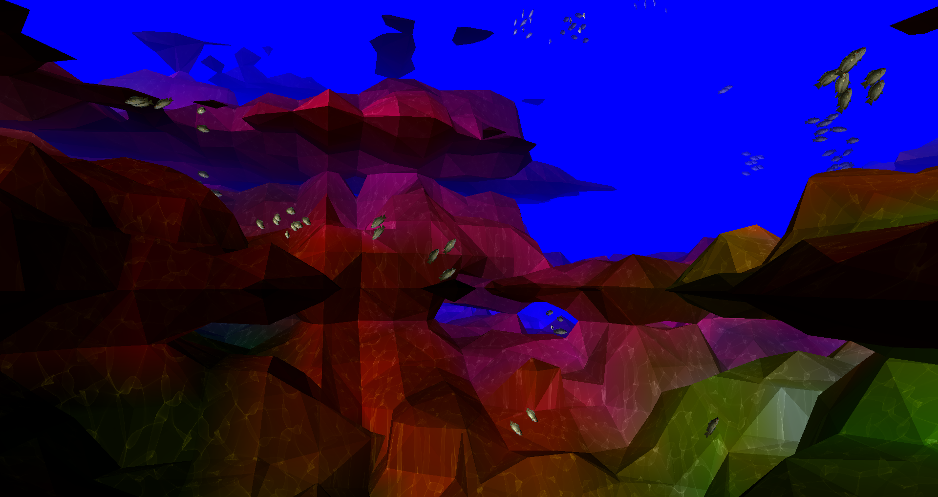
The Final Result
So after all of that, and a lot more is put together, we have a finished scene. This was one of my all-time most favorite and hated projects. I hope you all enjoyed it. Here’s a final demo:
]]>

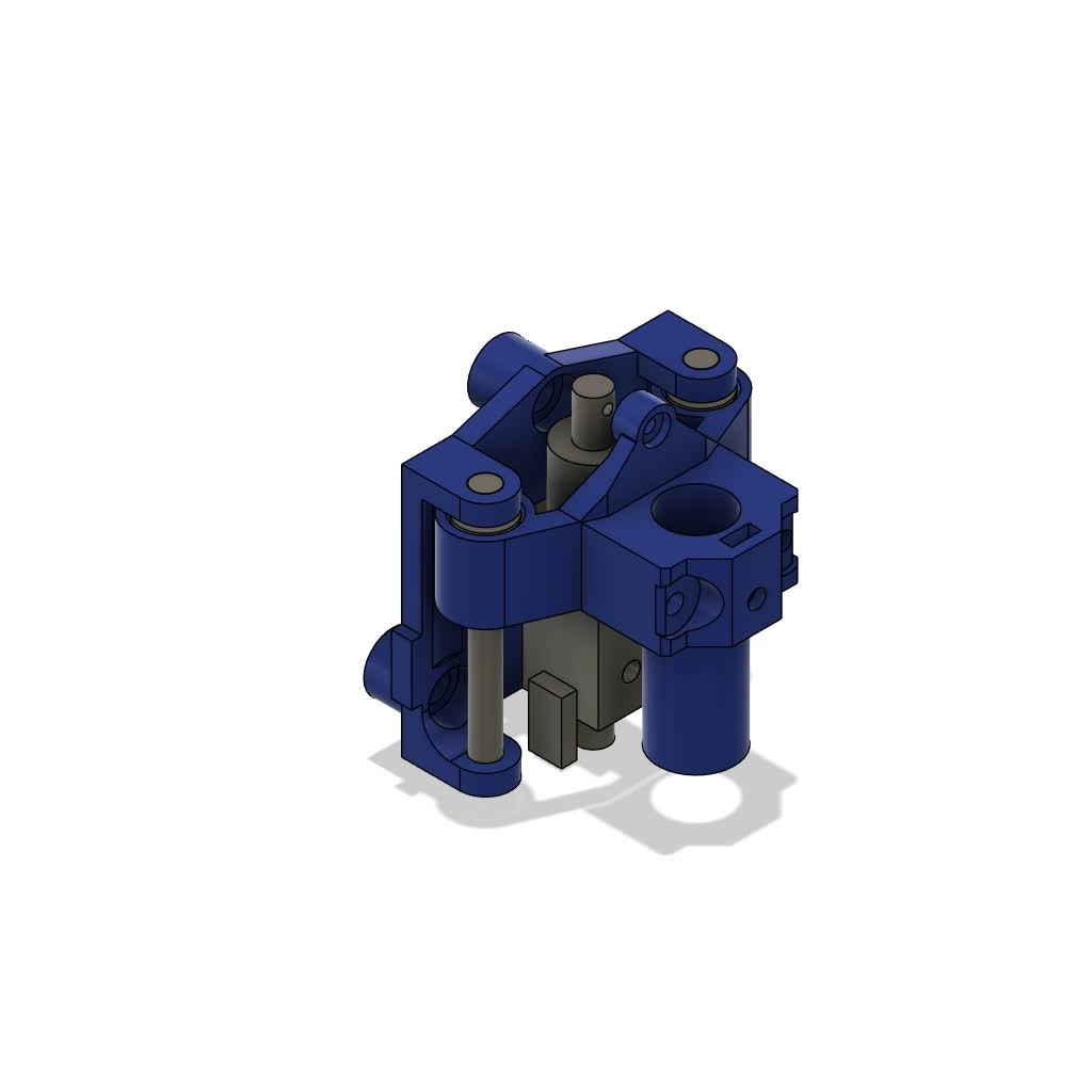


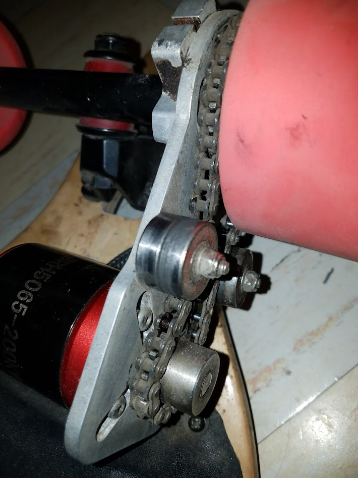
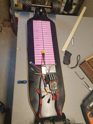
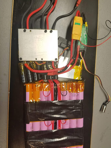
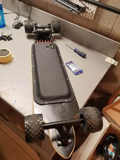
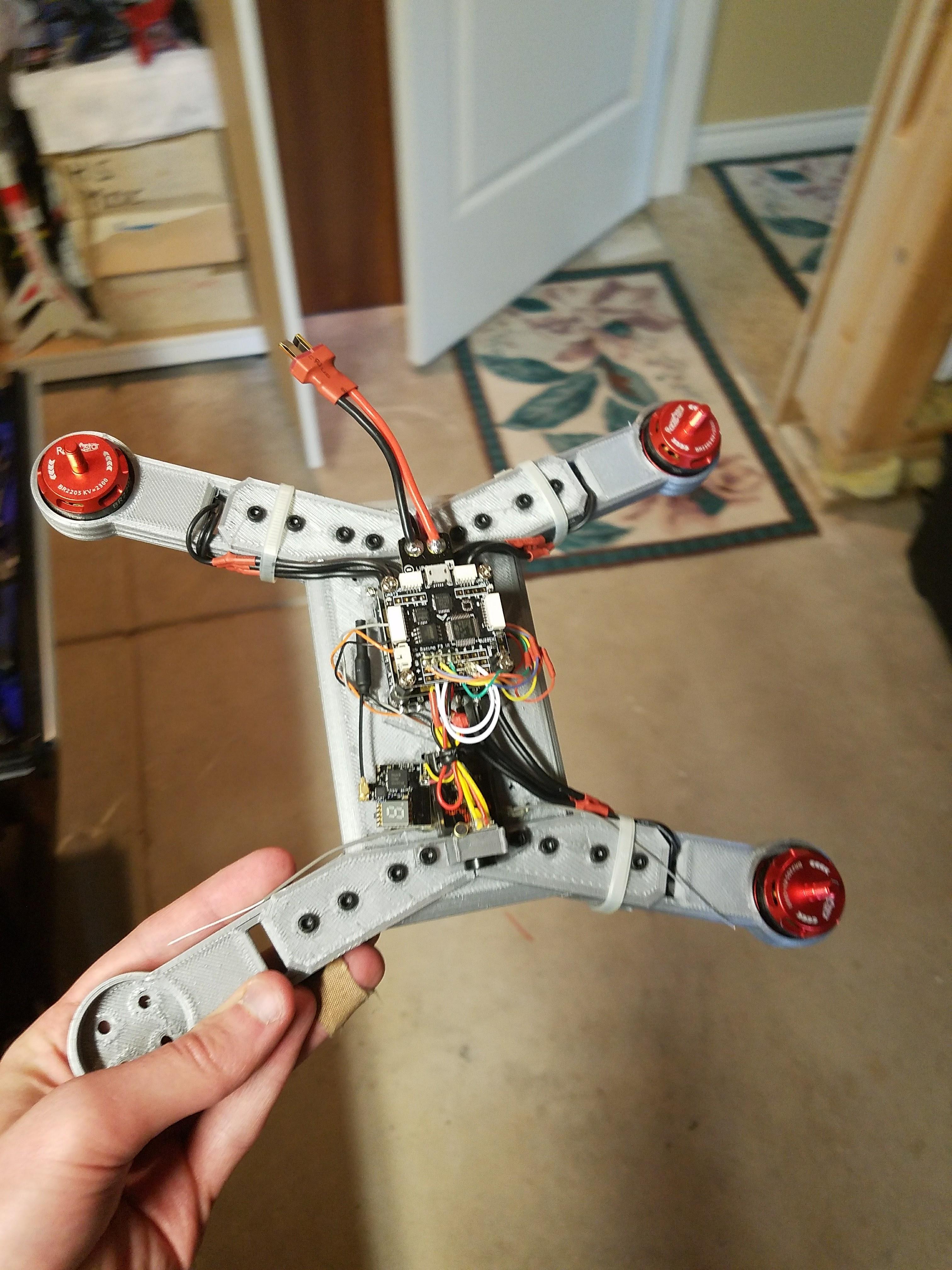
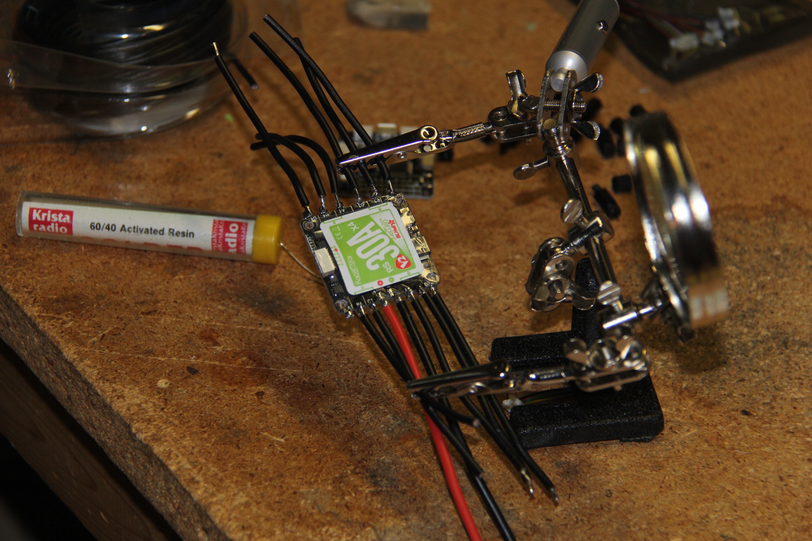 Wiring up the ESC.
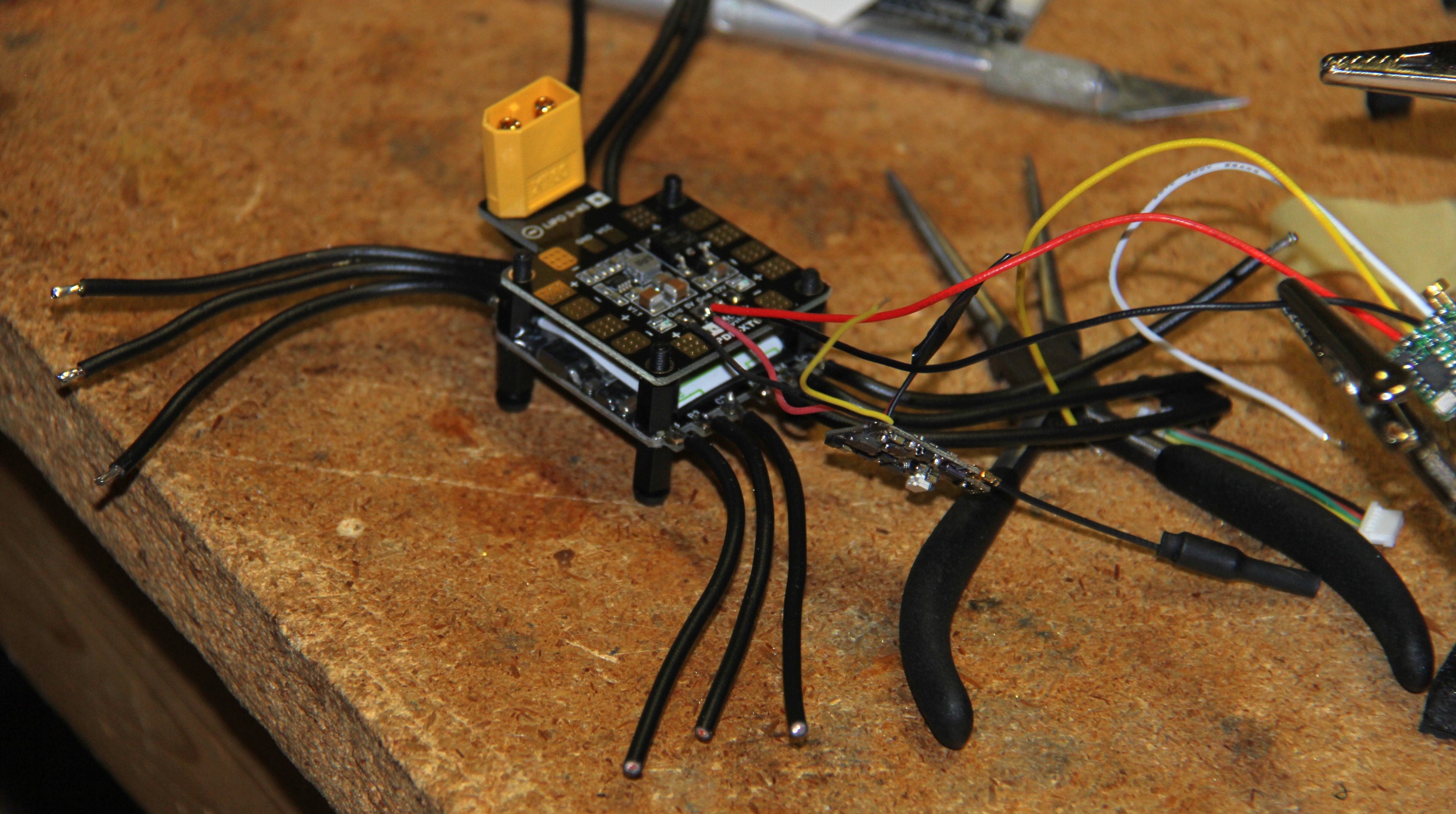 ESC goes on the bottom, PDB in the middle, and the FC goes on top.
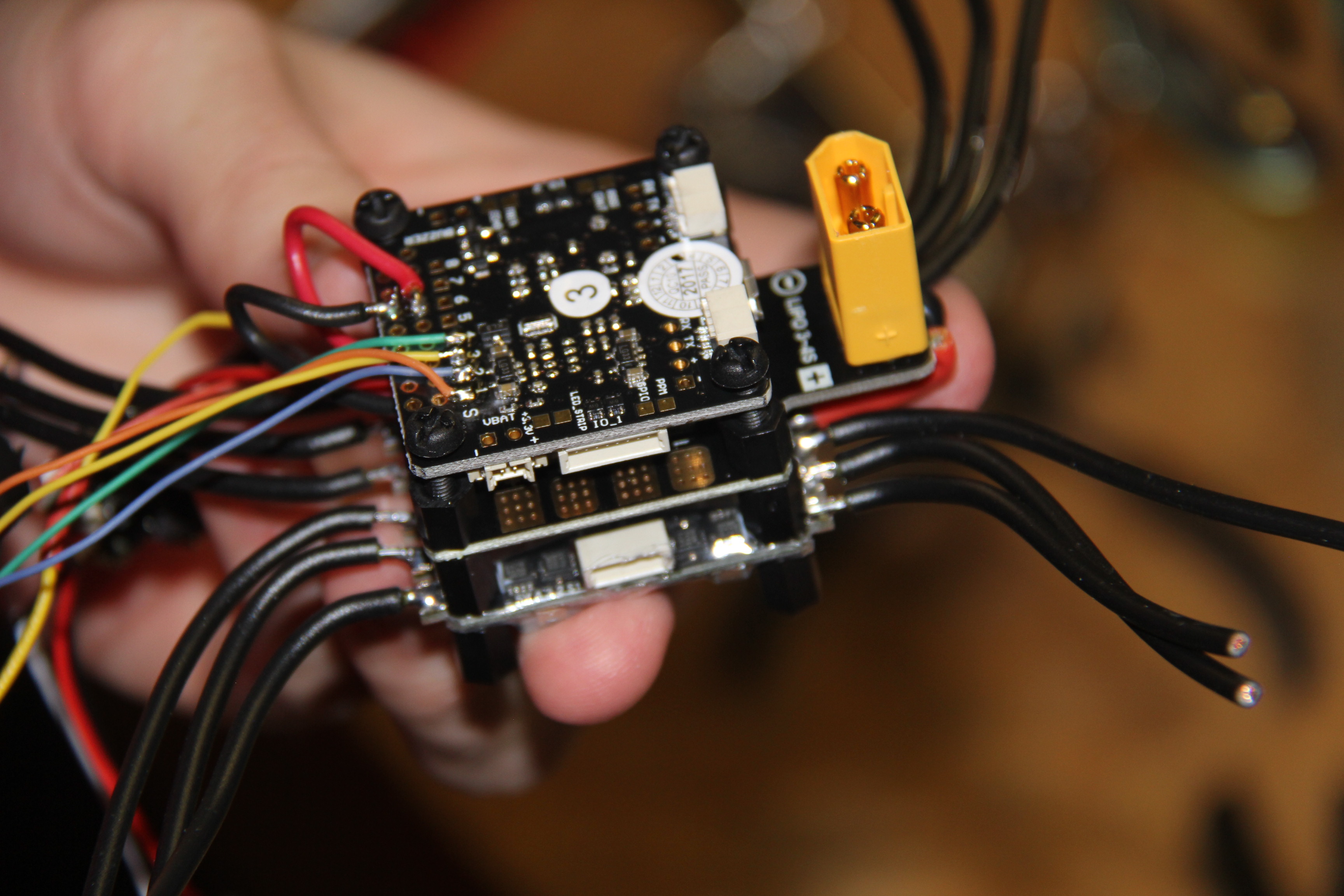
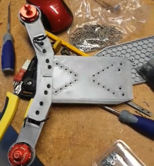


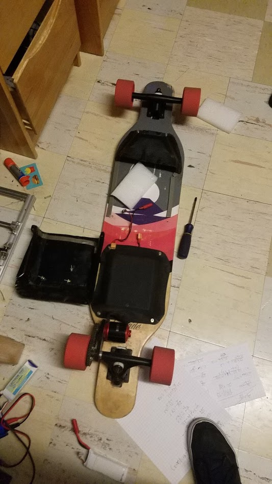
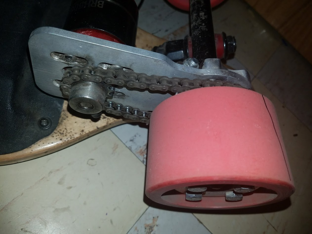
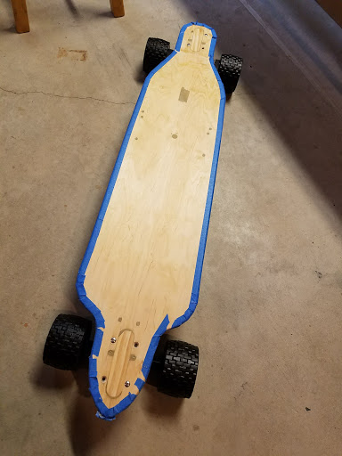
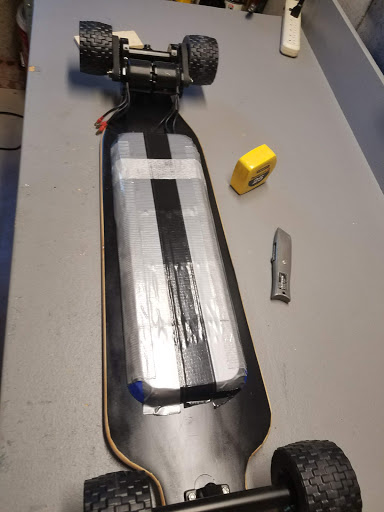
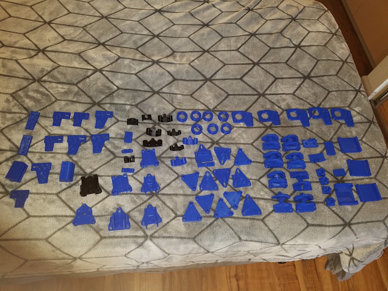
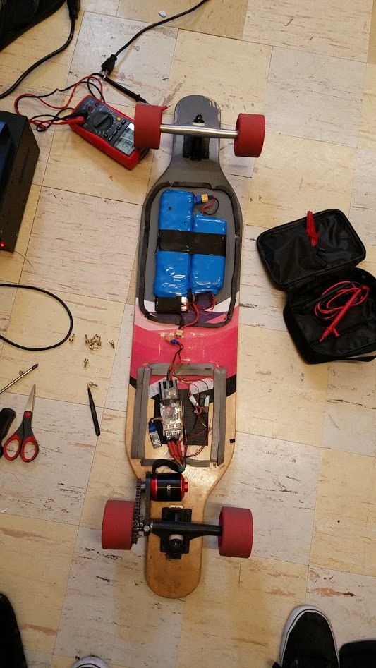 Also notice how the front truck is silver now. I snapped my front truck after running into a railing. Be safe!