3d Printing a 3d Printer With A 3d Printer
3d printers are really cool. You put plastic in, and it spits out highly detailed parts. By building a 3d printer, I wanted to learn how these devices work and possibly save a few bucks. First comes the model.
This was the first project I modeled using CAD software. It’s actually the first real engineering project I embarked on. I didn’t know where to start, so I just went with the most flashy option I could find in terms of software. I started with a cracked version of Solidworks; there was no way you could get me to pay $4,000+ for a program I didn’t even know if I could use. Anyway…
Back to the model. Here are some of the worst models I have ever made. Without any prior CAD instruction on how to use CAD, I would say these aren’t too bad.
Attempt 1
This is a prime example of me having no idea what I’m doing. I just took some parts and joined them together. It didn’t turn out very well.
This is not good. I don’t really know what I was going for with this design, but it offered a good lesson in how to create and join different components.
Attempt 2
Okay. Let’s try this again. I needed a more rigid frame. For that, I went online and drew inspiration from different 3d printers that I found in Google Images. There’s no hiding that the Prusa I3 is the most popular printer design out there, so my design copies the major features of the I3.
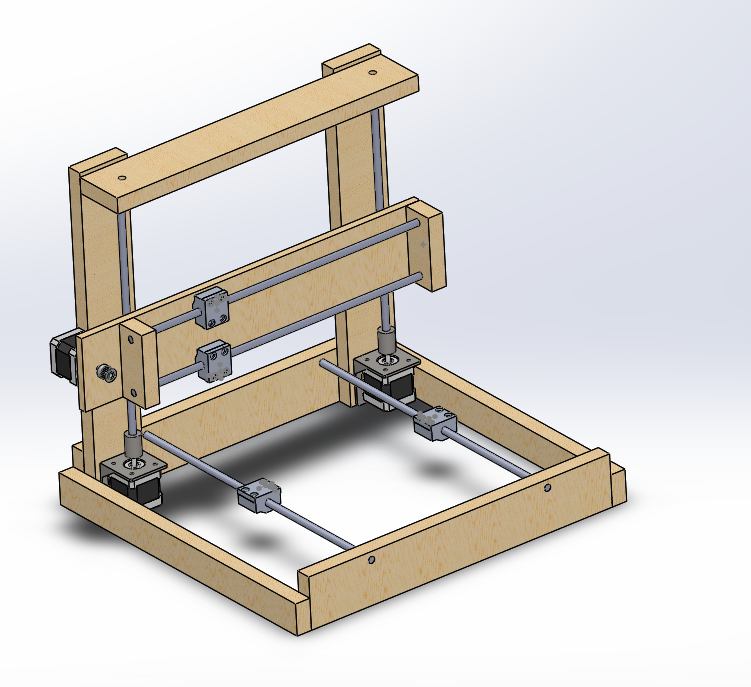
This is quite a big leap in terms of the design. There are now three axes and a rigid-looking frame. It could use some improvements though.
Attempt 3
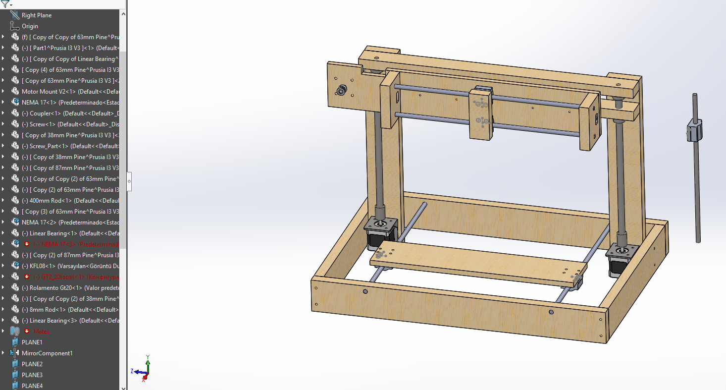
This took me several hours to get right. I even had Solidworks crash several times while I was designing the model and had to restart more times than I would have liked to. That’s likely because Solidworks is written for high-end workstations with $10,000 graphics cards.
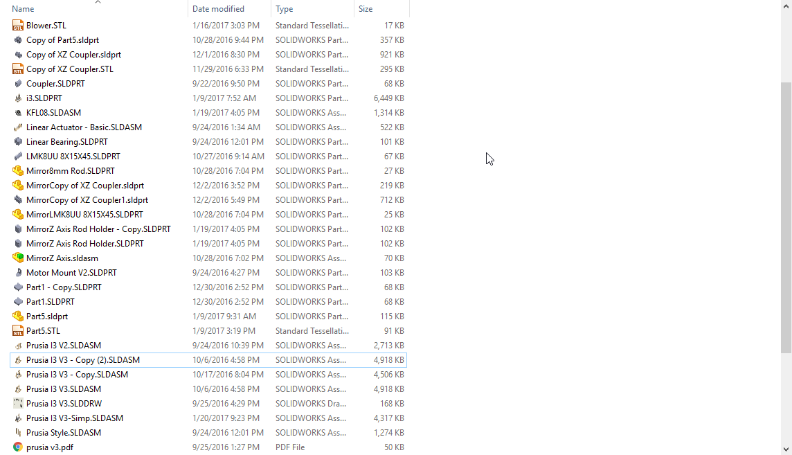
It’s still not that good. But it was definitely an improvement over the last one, featuring three axes instead of one and looking much more rigid. There are some major problems though. I included the sidebar to show that the model is a mess. References are missing, nothing is organized, and there’s a random X-rod just hanging outside the model.
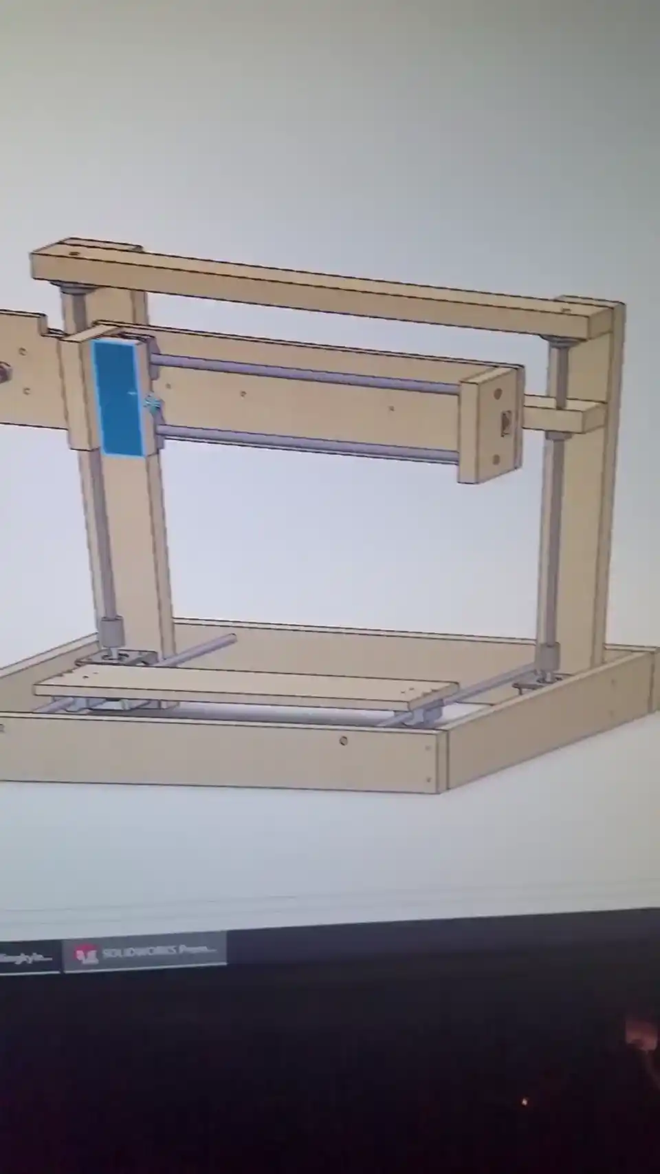
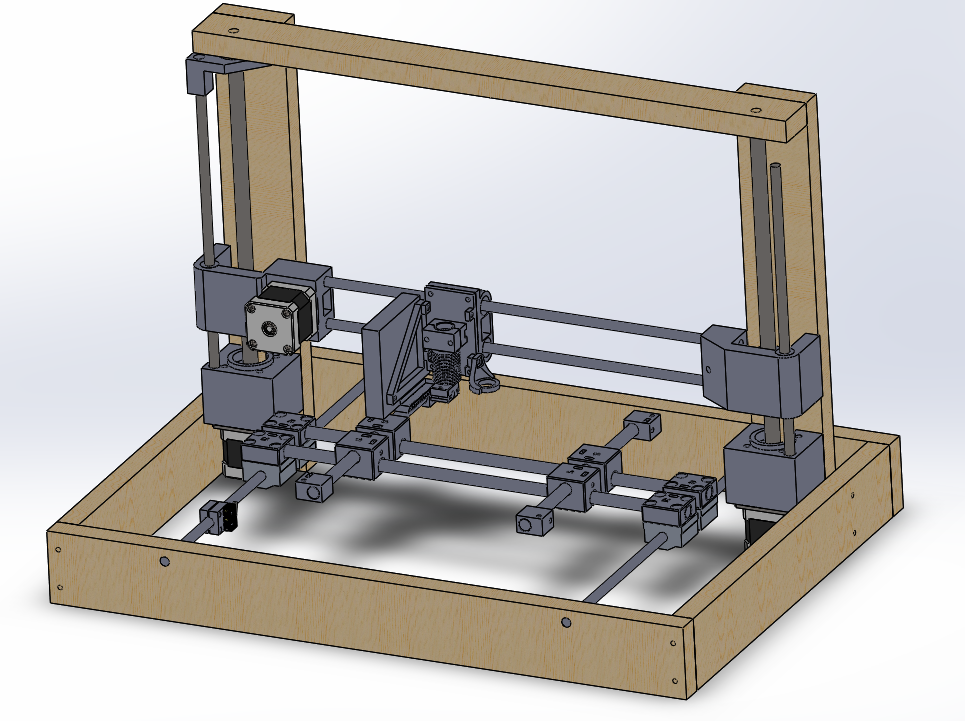
Attempt 4
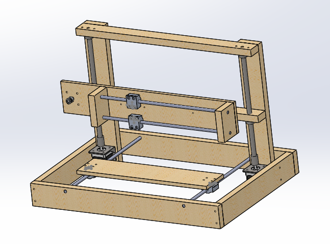
This is just Attempt 3 but with a few touch-ups. This is something that I can make.
Building
For materials, I decided on some wood from a local Lowes. It’s affordable and I can get as much of it as I need. I have access to a chop saw, so accurate cuts are pretty straightforward to achieve. The most challenging part is going to be making the parts precise enough so that it all fits together. My Dad has quite a bit of experience when it comes to woodworking, so I enlisted him to help me on my project. Thanks Dad!
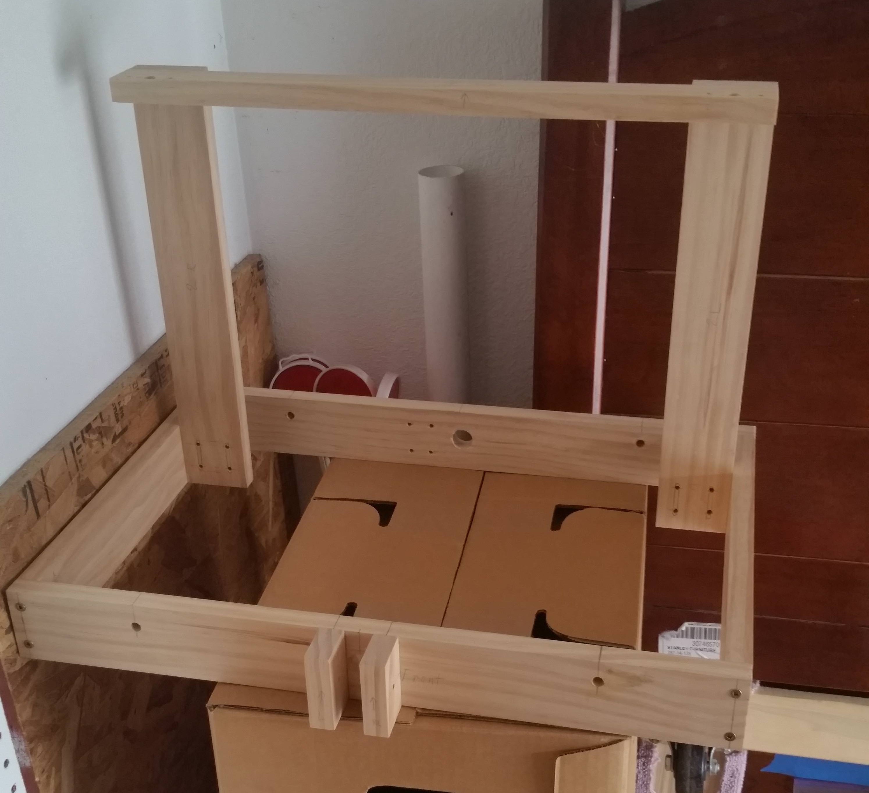
It took a lot longer than I expected to measure and cut everything, but it was worth it.
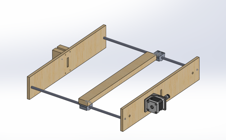
Continuity Error
I write these posts after I finish building something. Sometimes I forget to take pictures of some of the steps along the way. Here’s what I forgot to document. I made the X-axis carriage, installed some linear rods, bearings, steppers, and belts. Just like that, I had the worst 3d printer ever made.
I didn’t have any 3d printer components yet, so I duct taped a pencil to the end and tried to draw some things. These drawings didn’t turn out very well as the belts aren’t even tight at this point.
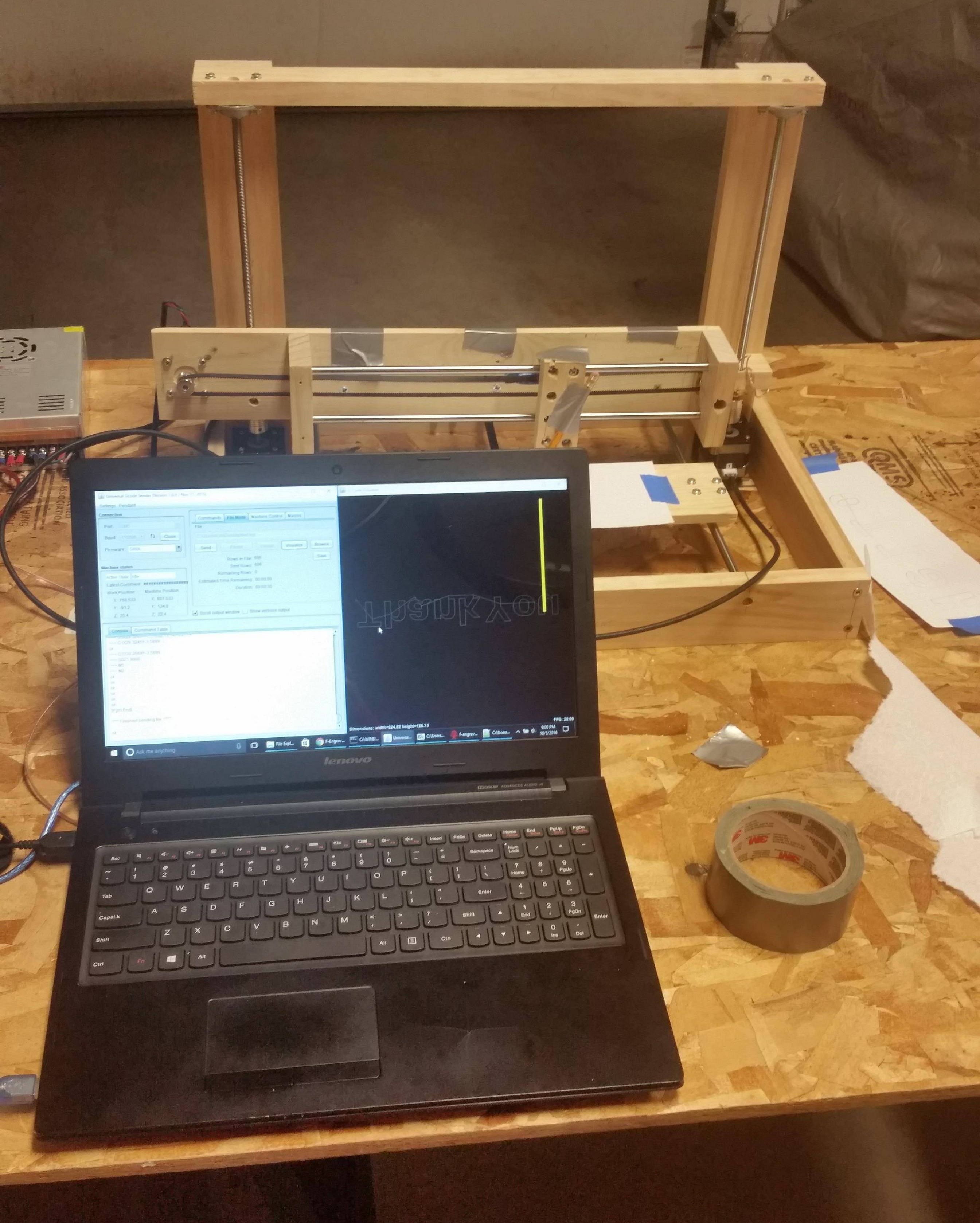
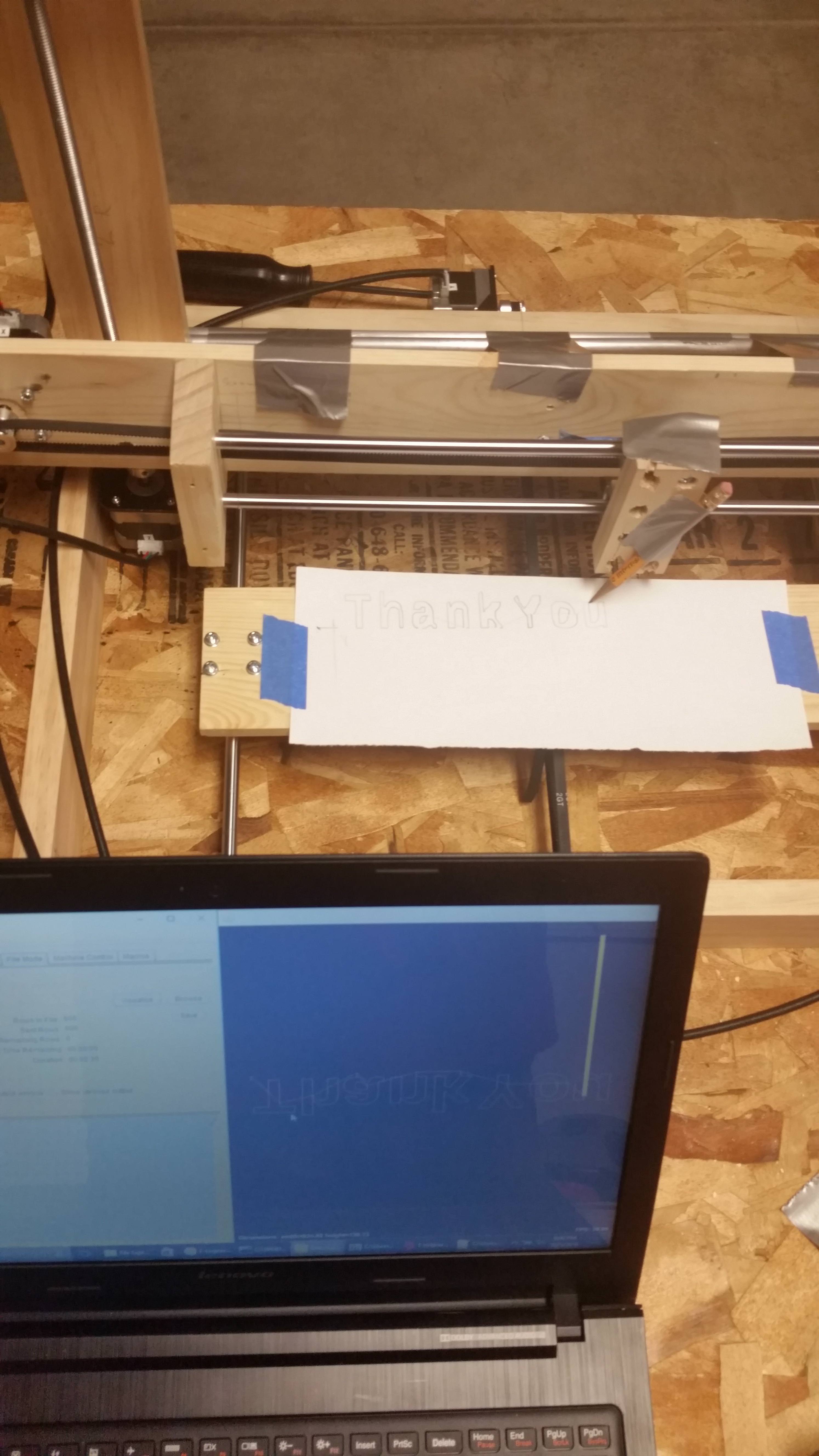
There are some serious problems with this design though. The X-axis is supported completely by the threaded rod, the Y-axis is a piece of wood, and don’t get me started about the X-carriage.
Back to Solidworks.
Attempt 5
I am encountering a lot of trouble trying to backtrack through this project because I have this cluttered directory full of random files.
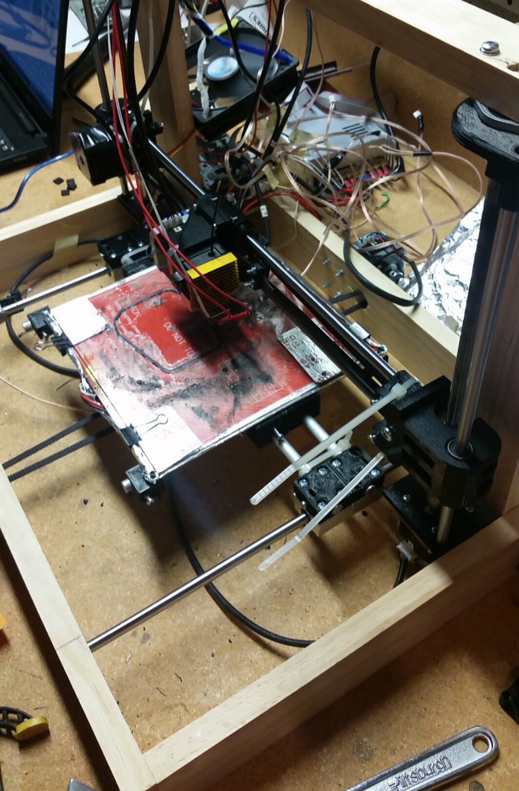
Back to the new design. I wanted more stability, the ability to hold a heated bed in a rigid manner and to completely redesign the X-axis. So I got to work with a now-assembled 3d printer. I also got rid of the wooden bed and replaced it with this new heated bed.
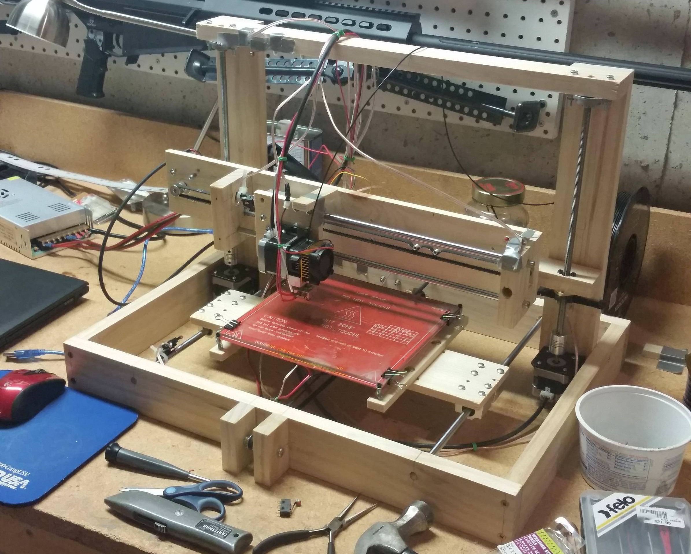
First revision that actually prints.
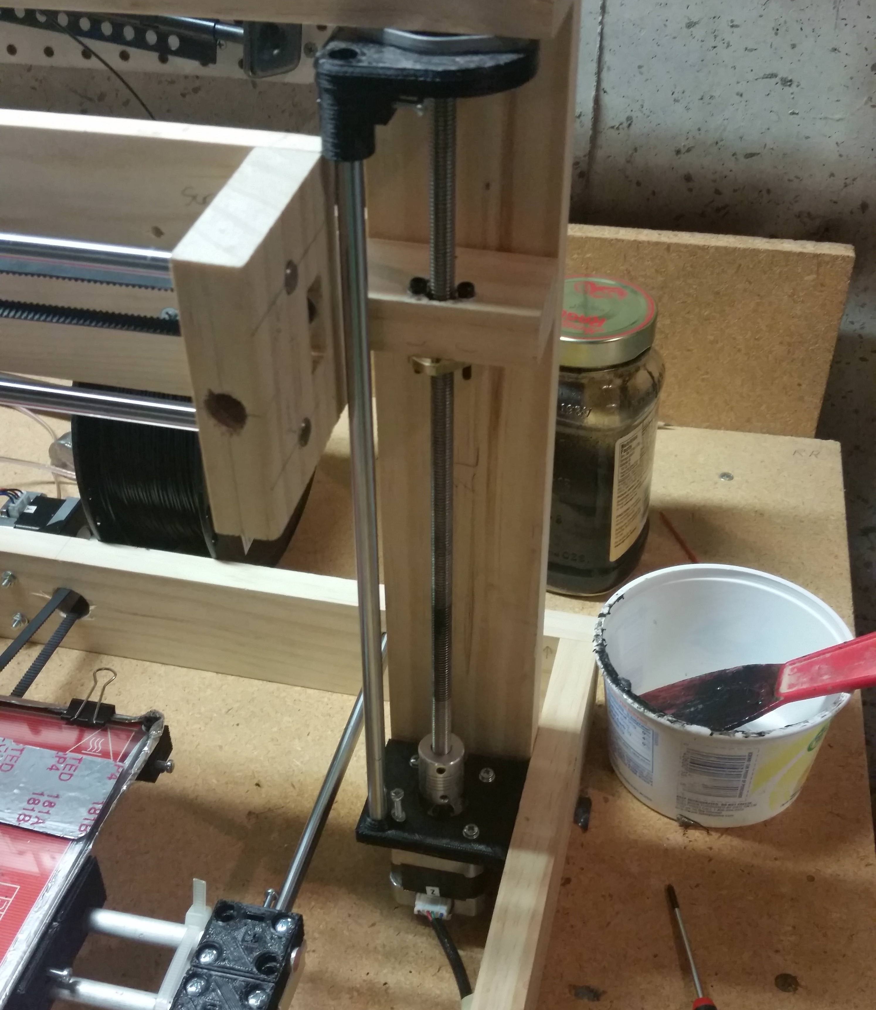
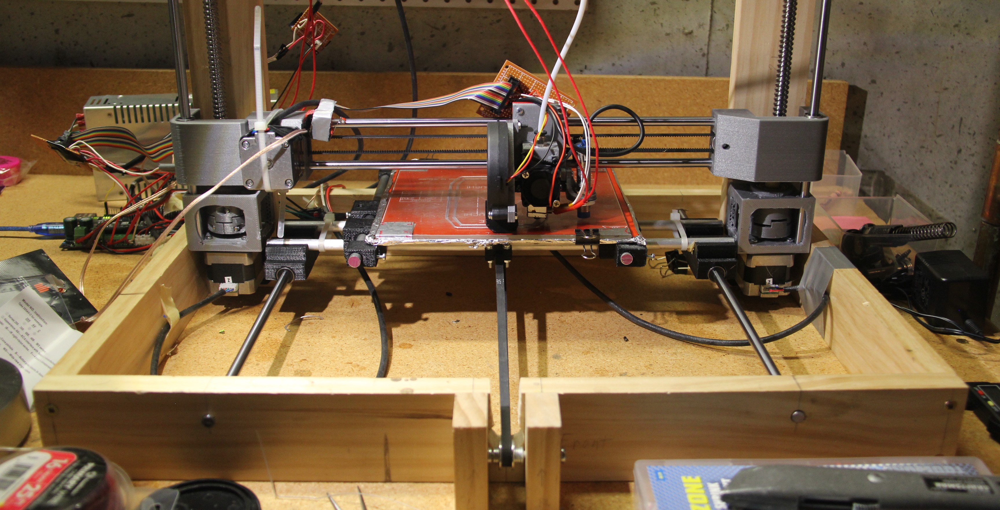
More support.
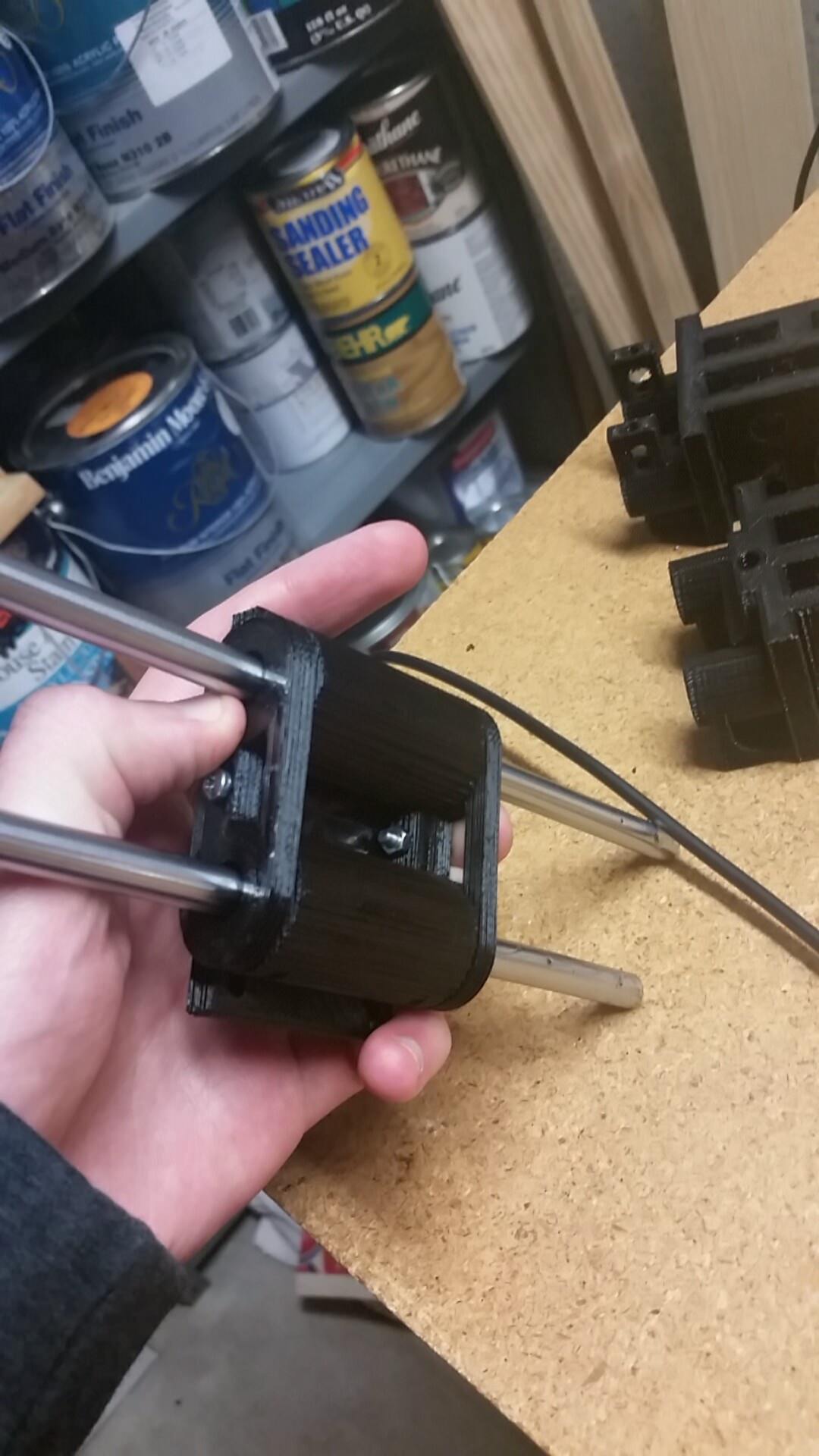
New X-axis.
Revision 5 complete!
Revision 6 and beyond
After revision 5 I took a long time looking at the downfalls of the current design and how I could make it better. One of the major weak points was the brackets that connect the Z-axis to the X-axis. Also, a Bowden extruder would be nice.
I took several months to get to this design and spent well over $600 to get a printer that performs no better than a $200 printer. But I learned a lot over the course of this project. I am really happy that I was able to make something physical for a change. For so long I had been working on programming projects, it felt good to do something different for a change.